The S.T.E.V.E.N. Solar Collector
>>> Instruction manual (please read description below first)
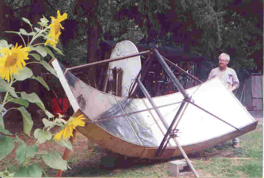
Our parabolic trough solar collectors generate heat and steam, which can then be used for pumps, engines, refrigeration, and other purposes. The trough concentrates sunlight falling on an 8 ' x 12' (or 10' x 12') area onto a 3 " diameter iron pipe, or "boiler." (Flat plate collectors used for hot water heating in many places do not bring the water to a boil.)
The trough underneath and to the sides of the boiler consists of three 4 ' x 8' (or 4 ' x 10') pieces of galvanized sheet metal, to which we attach mirrorized Mylar plastic, creating a "flexible mirror." We recommend the use of three plates because with the same investment in the boiler and other metal hardware, the builder gains an additional 32 square feet of insolation. However, if resources are limited or the application does not require the additional steam production, the collector can easily be produced in a smaller two-sheet version.
The reflective plates are set into a wood or metal parabolic frame, created using a paper template we supply along with the building instructions. While the Mylar is the most costly material in the collector (US$25 to $100 depending on quality of plastic, 1997 prices) and to the best of our knowledge must be imported from the U.S. or other industrialized country, with proper care it lasts 8 to 10 years in the field, so that its payback is assured.
With a little ingenuity, people can obtain locally all of the other materials specified (or some satisfactory equivalent) for building the collector frame. We recommend cutting a pair of parabola-shaped lateral ribs out of plywood, and then spanning the length of the collector between them with 2"x4" planks (or equivalent: in Taiwan we had 1"x3" boards custom-cut out of a heavy type of pine). This frame is suspended from the boiler using an angle-iron structure. In some places it may be more economical to make the entire structure out of angle iron.
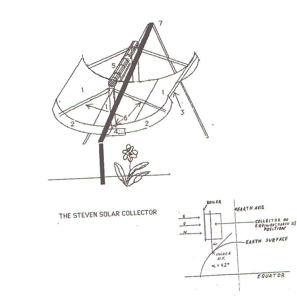
An additional mechanism allows the operator to vary the angle of the collector with respect to its axis of rotation, thus accommodating seasonal changes in the angle of incidence of the sunlight (angle at which sunlight strikes the collector). The position of the turning axis can be adjusted so that the collector remains as perpendicular as possible to the sun as it rotates through out the day.
Back to the S.T.E.V.E.N. Homepage...
Thermal Collector Tracking System
Our automatic solar tracking system for the collector follows the sun throughout the course of the day by constantly sensing whether the collector is aligned correctly with the plane of incidence of the sunlight. This system uses a heat-sensitive valve, a hydraulic "crutch," and a length of narrow (1/8" i.d.) tubing to connect the two. The several parts are shown in the diagram.
![]()
The tracker works as follows: the collector is weighted so that it will tend to rotate toward the west on its axis of rotation. The hydraulic crutch then supports the weight of the collector, and allows it to rotate only as water is allowed to flow past the valve in the tracking mechanism. The tracking mechanism uses the expansion of an aluminum shaft to open and shut the valve: as the sun advances and the shaft emerges from the shade along the edge of the collector, the aluminum expands and opens the valve, allowing the collector to rotate until the mechanism is in shade again and the valve closes.
Back to the S.T.E.V.E.N. Homepage...
This section describes three water pumps developed by S.T.E.V.E.N. Foundation research. Each serves a specific need. The shallow lift pump is the simplest to build, but only works from shallow depths. For deeper sources of water, the hydraulic pump permits pumping from much greater depths. Alternatively, the shallow lift pump can be adapted so that the valve chamber is below ground and is connected to the pump handle using a shaft. The solar surface pump is also for shallow sources of water, but uses steam injection from a solar collector or other source, rather than hand power, to generate pumping action.
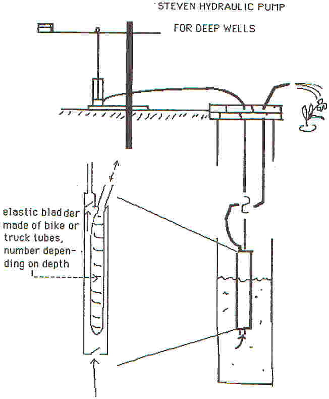
The example below shows a complete hand pumping system including water source, piping, pump handle, and in the case of the hydraulic pump shown, a bladder unit:
Shallow-lift pump ("Ten-dollar pump")
The shallow-lift pump was developed in Mexico in 1990 to provide low-level lift from shallow aquifers, and also to replenish rooftop reservoirs at minimal cost. We sometimes also call it the ten-dollar pump since the materials to build the pump can be purchased for this amount, although actual cost may vary from this average based on local materials costs and the design of the pump handle. In Spanish we call it the vacuum pump since it works based on the principle of evacuating a cylinder, attached by a short shaft to a 1.5 to 2 meter handle, by which the user pumps to create suction. Therefore the bottom of the pipe leading into the cylinder may be at most 8 vertical meters deep, due to the hydrostatic limit. At greater depths we recommend any pump which propels the water from the bottom up rather than using suction at the surface such as the S.T.E.V.E.N. hydraulic pump, or a conventional deep-well pump. At the output end, the vertical distance water can be pumped is limited only by the strength of the person pumping.
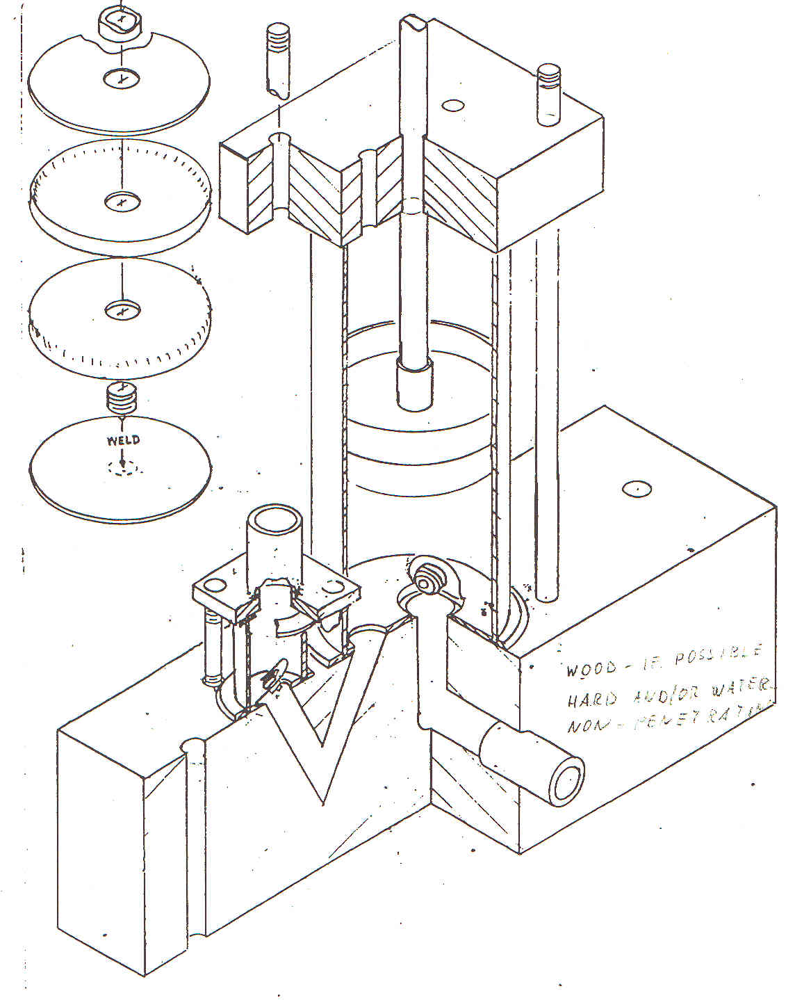
The heart of this design consists of a base plate made of a 1 length of either ¼ x 4 steel or wooden 4 x 4", to which inlet and outlet valves, built from scratch in the case of the diagram, are attached. We then fasten the cylinder to this plate by passing two lengths of threaded rod through the base plate and the guide plate atop the pump, and tightening the whole pump together. The guide plate also directs the motion of the piston shaft, to which we attach a piston made up of two circular metal disks sandwiching two leather cups. The main tools required for this construction are a drill with bits up to ¾, an electric grinder, and a sabre saw.
Once this pump unit has been completed, it is mounted on a handle and stand which the owner can design to fit her or his own needs. For example, since pushing down is easier than pulling up when pumping the handle, if the owner is pumping uphill from the pump she or he should mount the pump on the same side of the central pivot as the handle. Accordingly, if the user is pumping up to the level of the pump she or he should position the handle on the opposite side from the piston.
Back to the S.T.E.V.E.N. Homepage...
Along with its pump for shallow-lift pumping, S.T.E.V.E.N. Foundation has developed a hydraulic pump for depths equal to or greater than the hydrostatic limit of 32 feet or roughly 10 meters. The system involves three parts: a 'piston unit,' a 'bladder unit,' and a hydraulic column. The piston unit provides the handle for pumping from the surface. The bladder unit includes a chamber in which the expansion and contraction of a rubber bladder propels water past an inlet and an outlet valve. A hydraulic column sealed in a length of flexible PVC pipe then transmits the pumping force from the piston to the bladder. A second length of PVC transports the water to the desired destination, which need not be adjacent to or at the same elevation as the piston unit location.
Shown below is a double-action variant of the hydraulic pump, with two pistons attached to the handle for extra pumping capacity:
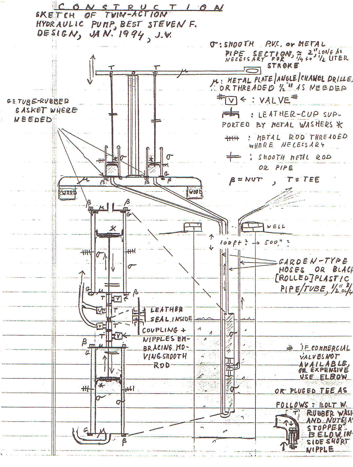
Developing a bladder sturdy enough to withstand continual expansion and contraction is the key to the success of this pump. With a sufficiently stiff bladder there is no specific limit on how deep this pump can be placed: our own experiments have been conducted at depths of up to 170 feet. We are still in the process of designing the optimal solution.
Back to the S.T.E.V.E.N. Homepage...
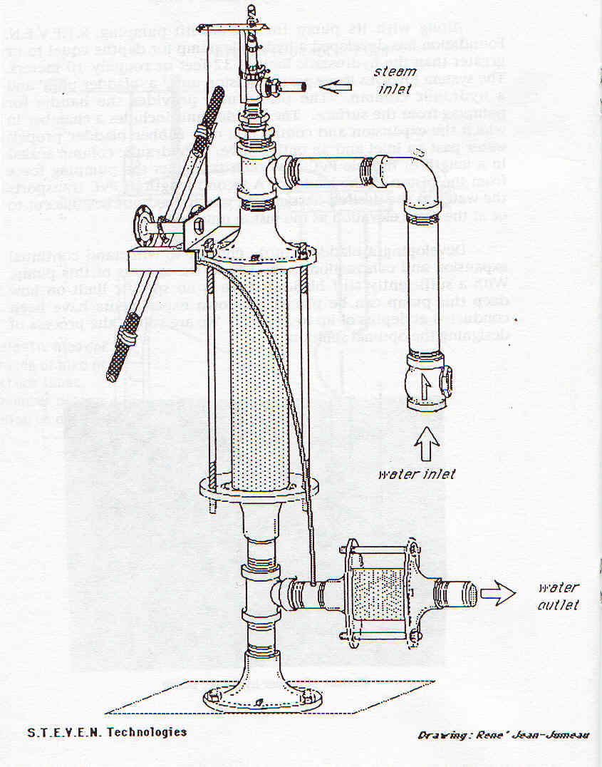
S.T.E.V.E.N. Solar Surface Pump
S.T.E.V.E.N. Foundation has developed a device that converts steam generated by the parabolic trough collector directly into water pumping power, without the intermediate use of a steam engine to convert the thermal energy into mechanical motion. We have named it the "Solar Surface Pump" since the force which moves the water from the source to its destination is suction supplied at the surface. Therefore, the version of the surface pump included here functions within the hydrostatic limit. However, parts of the surface pump design are included in a patented "deep-well pump" (not shown here) which can exceed that limit.
If constructed exactly according to our manual and the accompanying diagram, using parts purchased in the United States, the cost of the surface pump would be approximately US$40. However, with appropriate (and given availability in other countries, sometimes necessary) part substitutions -- especially, replacing threaded junctions between parts with welded seams--that cost estimate can be reduced. The surface pump can be built with a basic collection of power tools, including an electric drill and grinding wheel.
The surface pump design exploits the properties of steam in two phases to move the water through its trajectory. First, starting with the central chamber in the pump already filled with water, steam enters from a spring-loaded injection valve to drive the water past the outlet valve and out of the pump. Once the steam has emptied the main chamber, it immediately condenses because of the ambient temperature, creating a vacuum which sucks water from the source past the intake valve and into the main chamber. The cycle then repeats itself. A weighted pendulum attached to a bicycle hub releases the injection valve once per cycle so that the steam will enter the chamber at the correct time. Because of the cyclic motion of the pump, and the direct contact between the steam and the water being pumped, we also refer to it as the "open cycle pump."
The open-cycle has the advantage of combining the conversion of power from steam to mechanical, and the pumping action, into a single device. However, it also has some disadvantage in that it is prone to overheating and stalling with prolonged use. Although we welcome experimentation with this design by others in the field, we also promote a traditional hand pump (such as the shallow-lift pump above) combined with a steam engine, as discussed in the next section.
Back to the S.T.E.V.E.N. Homepage...
Our steam engine was originally developed as a means of converting the steam generated by the parabolic trough solar collector into all-purpose mechanical force. A team of metal workers can assemble the engine in a day with materials costing about $50 at US prices (1997), and a basic set of electric tools (drills, hacksaws, electric grinders). On the limit, it can be made with only hand tools. The engine minimizes dependence on outside assistance: it is light enough to be distributed to a rural region which does not have access to electricity from a shop in an urban setting, and once installed it can be serviced with hand tools on the site.
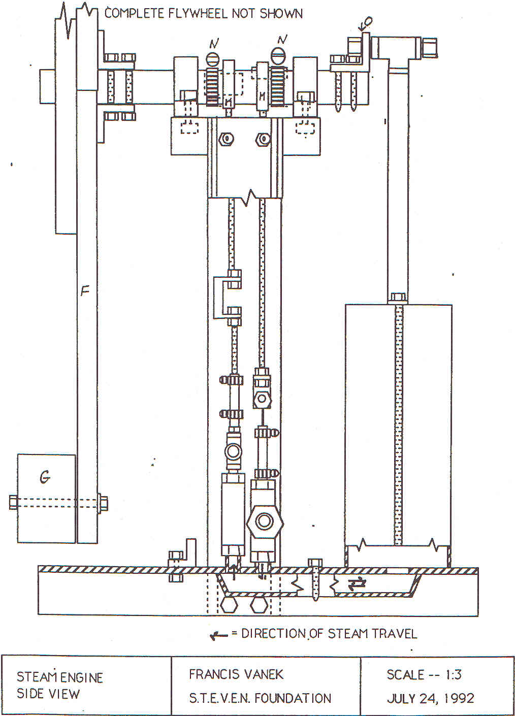
The engine can be divided into two parts, a cylinder-crank- flywheel assembly and a frame. The cylinder is fastened to the frame using a gasket and two threaded rods with clamp (see the drawing). A piston made from two metal disks sandwiching rubber gaskets moves vertically inside the cylinder, rocking gently while preserving a perfect seal, rotates the I" steel drive shaft (attached to the frame with a pair of cartridge bearings) and the 40 to 100 lb. flywheel. We assemble the frame from two horizontal and two vertical lengths of iron U-channel (aluminum or wood might also be used) so as to use the precision of the right angles to guarantee that the drive shaft will turn parallel to the base of the engine, minimizing friction.
As shown in the detailed drawing, the two valves operated by the drive / camshaft let steam in and out through an adapted angle iron below the base U-channel. The valves are produced out of off- the-shelf plumbing parts. The outlet can be linked to a simple vacuum-condensation system: thus our engine becomes probably the simplest and least expensive pressure / vacuum engine in the world, with power considerably higher (for the same steam input) than a steam engine which releases used steam into the air.
Attached to a solar collector or other source of low- or medium-pressure steam, the engine can drive many types of mechanical applications. It serves especially well for long-duration activities which require only a moderate power output, such as attachment to either a shallow-lift or hydraulic pump to irrigate a field for several hours a day on a regular basis.
One of the great advantages of the mechanical power provided by the steam engine is its versatility. The spinning shaft of the flywheel can be connected, either directly or through the use of a chain drive, to a grain grinding mill, a potting wheel, a circular saw blade, or an electric generator. Alternatively, the user can mount a crank and connecting rod to connect the engine to a reciprocating pump, as mentioned above, or an agitating clothes washing machine.
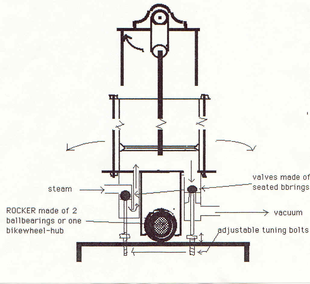
The Rocking-Piston Engine (1995)
Further research led in 1995 to a number of alterations of the steam engine design. Important aspects of this newer engine are (1) separability and (2) simplicity. It consists of two parts: the flywheel and power take-off, and the power assembly. The entire mechanical portion is reduced to a rocking platform, on top of which we mount any heat-resistant smooth cylinder with piston and shaft moving parallel to the walls of the cylinder. The accomodation to the motion of the crank is performed by the rocking motion; and this motion in turn opens and closes the ball-bearing-seal valves at the bottom of the platform. The great advantages are simplicity, directness of motion of piston allowing higher pressures, and much longer stroke--as long as permissible by the distance between the platform and the crankshaft. The special motion inclines us to nickname this the "penguin-walk" engine.
The separability can best be understood in the following way. Anyone can build his or her pump, electric generator or other application with a suitable flywheel and crank-eccentric. The wheel and crank can be turned by hand if necessary. The builder can even provide a pipe and corresponding piston and then use a standard rocking platform, producible or purchasable from a specialized coop or individual firm which can produce a series of such instruments.
Valve seals on the steam engine were also modified. While the original injection and steam control valves are still considered good, we now use valve seals based on ballbearing balls of various sizes, which close a seat formed either by a polished bushing, or by drilling a larger hole over a smaller one concentrically. The opening of the valve is then performed by poking from below with a poker sealed in the valve through thick rubber tubes or silicone. Such valves make it possible to build up higher pressures, and work toward greater efficiency of the steam engine.
We have identified one small disadvantage of the "penguin" design compared to the older engine. While the vacuum cycle (from noon to 6 pm) can be perfectly timed and tuned, the expansion cycle tuning is slightly restricted because the angle of opening the injection valve determines also the angle of its closing. But this has probably an infinitesimal effect on efficiency.
We consider the new "penguin-walking" engine to be superior in several respects:
1. Tremendous robustness and precision of its valves made of ordinary
ball bearings.
2. Continuous self-fitting and polishing of the valve surfaces.
3. Simplicity of construction.
4. Power-shaft always aligned with the cylinder, so that the piston
seals are much more reliable and do not wear out.
5. This serves especially the vacuum-part of the cycle, which is now
easy to install and quite reliable because of the improved seal on the
piston.
6. Perfect separability of the engine base from the rest, especially
from the flywheel which can be constructed first with the pump or other
"manual" application and then the steam part [about 4" x 4" cube for a
3" piston].
7. The pendulating motion of the assembly makes it very easy to attach
a miniature pump, which sends several drops of water back into the boiler
with each stroke of the engine.
Back to the S.T.E.V.E.N. Homepage...
S.T.E.V.E.N. Solar Oven-Cookers
>>> Instruction manual (please read description below first)
After using our basic one-foot-square cooker extensively for a number of years, we have developed a new design for oven-cookers of various sizes, all one foot deep, with approximate dimensions 1 x 1, 1 x 2, and 3 x 3 feet. The first two are designed for family use while the third can serve bakeries of larger communities, with a capacity of up to 100 loaves of bread per day in full sun. The principle of heating the box by a four-sided cone of reflective material (typically Mylar plastic) mounted on rigid, weather-resistant backing remains unchanged.
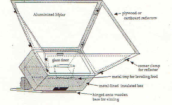
The new design permits temperatures comparable to normal kitchen ovens, or approximately ambient temperature plus 350 degrees Fahrenheit. It thus becomes possible to cook, bake, or roast just about anything, from bread to chicken to steak to beans or rice or spaghetti, and so on. Cooking times are somewhat longer than in a regular kitchen situation, especially where food is to be boiled in water. Frying in oil is also possible, but with significantly lower efficiency. Our construction drawings can be used for the large and small oven, intermediate dimensions being readily adaptable.
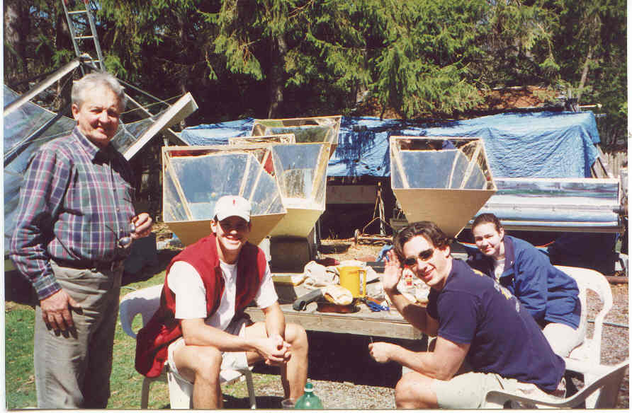
Cornell University students with home-built solar ovens in background.
Field applications of solar ovens: Bolivia, Haiti (Rural), Haiti (Port-au-Prince), Philadelphia (we're not kidding!), Peru.
Back to the S.T.E.V.E.N. Homepage...
>>> Instruction manual (please read description below first)
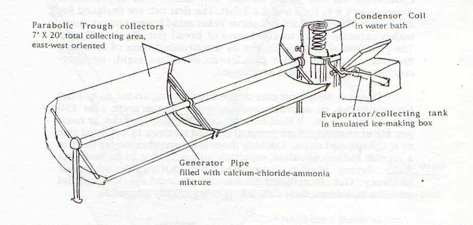
This design puts our standard solar collector to work as the energy supply for an intermittent absorption cycle refrigerator. A sketch and photo are shown. Basically the principles of ice making with this technology are evaporation of ammonia gas from its compound formed with calcium chloride within a generating pipe heated by a parabolic collector in east-west position. Such gas is then condensed into fluid ammonia in a coil resembling a still; and that fluid is deposited in an evaporator within the icemaker- refrigerator. Whenever the generating pipe [boiler] cools --typically at night--the ammonia in the evaporator starts boiling off at temperatures well below freezing. This then cools the refrigeration space and/or produces ice from water placed in the space.
We have now designed a mechanical (non-electric) temperature control device, and a system which will permit continuous operation at stable temperatures which are necessary for many medical and other applications. However this more advanced refrigerator is still it its final design and testing stage, and thus is not available for publication.
IMPORTANT CAUTION: It must be remembered that any work with anhydrous ammonia is risky, and should be conducted ONLY OUTDOORS and BY THOSE WHO ARE PROFESSIONAILY QUALIFIED FOR SUCH WORK. In either case, the drawings and illustrations in this prospectus are intended only for information and not as a construction manual. The S.T.E.V.E.N. Foundation declines all responsibility related to construction and experimentation with its technologies.
The current solar refrigerator- icemaker design is an improvement over our previous multi-stage design that involved connecting a moving (tracking) generator to a stationary still and refrigeration space, with ammonia passing from one to the other part. Given the harmful character and high pressure of ammonia gas, this increases considerably the risks of air pollution or even bodily injury. We recommend that designers avoid any moving or flexing ductwork when working with ammonia, as is the case with the design shown here.
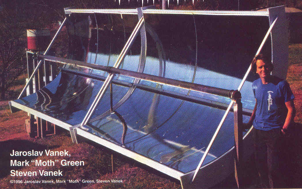
Field Testing of refrigerator-icemaker
We have also developed and have description available for a bicycle we call the "Vanek Superbike", or all-wheel-drive, hand-and-leg power bicycle. More information is available at www.people.cornell.edu/pages/jv19.
Back to the S.T.E.V.E.N. Homepage...