Please email any comments or questions to us at jv19@cornell.edu.
Introductory comment: the construction manual for this icemaker system consists of the article on its fabrication in Home Power magazine Issue #53 in June 1996, the additional notes on construction below, instructions for operation at the end of this website, and an instruction manual for the parabolic trough solar collector that is needed to concentrate the solar energy for boiling the refrigerant. (See the Home Power Magazine website to purchase a hardcopy of the article or a CD-ROM with an archive of articles including this one.) Step-by-step instructions for building do not exist at this time. However, we feel that a competent technician can use this soft manual to adapt the generic design to local conditions and construct the device.
Also, we plan to include the text and figures of the Home Power article in this website in the future, but it is not available at this time.
Important: notification of risks associated with working with solar absorption icemaker -- we are eager to see others work on this promising but challenging form of solar energy, and wish to encourage experimentation in the field. However, because of the risks associated with working with ammonia, which is both toxic and explosive, the STEVEN Foundation and its individual members hereby renounce any liability for accidents occuring due to work with this technology. Individuals wishing to pursue this technology should thoroughly understand the risks of ammonia before starting, take all necessary precautions, use materials and components with appropriate durability for working with ammonia, and seek professional expertise where they themselves do not feel competent to construct or activate the system.
Introduction
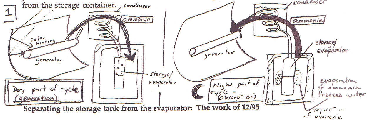
The original, simplest design of the icemaker involved three components: A solar-heated generator pipe, a condenser coil in a water bath, and a storage/evaporator tank. During a sunny day, ammonia is boiled out of the salt in the generator pipe and condenses in the condenser coil, dripping down and collecting in the collection tank. The collection tank is inside the insulated ice-making space. During the night, when ammonia is drawn back through the condenser coil into the salt in the generator, the evaporation of this ammonia absorbs heat from water that is placed in bags around the storage tank. Thus, the storage tank is not only a storage tank but also functions as an evaporator, the part of the refrigerator where ammonia evaporates and absorbs heat so as to freeze water. As presented in figure 1, the operation of the icemaker can be visualized as a back and forth flow of ammonia between the generator (solar collector end) and the storage/evaporator tank (icemaker end). Ice is only produced when ammonia flows back to the salt in the generator and evaporates from the storage container.
Figure 1
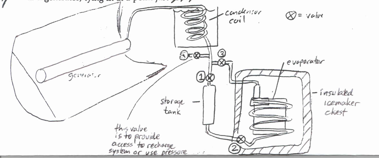
Over the past 3 weeks David Beasely of SIFAT and myself have attempted to improve the functioning of the icemaker. As it stands now, the icemaker consists of 4 components, illustrated in figure 2 below. The solar generator and condenser coil remain as above. However, the storage tank for ammonia is now outside the refrigerator. From the bottom of the storage tank, a pipe leads through a valve into the specially built evaporator which is inside the insulated icemaking space. From the evaporator, a pipe leads back to the condenser coil and generator, tying in at a point just below the condenser coil.
Figure 2
The improvements also involve several valves. These
are placed so as to direct the ammonia into the storage tank during the
day when the collector is generating. During the night, they are set so
as to seal the top of the storage tank, thus forcing the ammonia to pass
though the evaporator. The valve at the top of the evaporator is also opened,
so that the ammonia is free to evaporate back to the generator pipe.
Justification - There are two reasons for attempting this improvement,
which does complicate the plumbing and the operation of the icemaker somewhat.
- The first justification is aimed at using the icemaker space as a
refrigerated space, where the ice formed during the night cycle would keep
the space cool even during the day, when no ice is being formed. In the
earlier, simpler design, condensed ammonia entering the storage tank during
the day was cool, but not as cool as the temperatures one might hope to
maintain in an icebox. This ammonia warmed the space, and even with the
ice from the night before, on a warm day the icemaker box could be quite
warm by late afternoon. By storing the ammonia outside the icebox in a
separate storage tank, the ammonia will not warm the icebox during the
day.
- The other advantage of having a separate storage tank and evaporator
is that we were able to concentrate on specializing the evaporator to its
purpose, that of absorbing heat from the water. By making it out of a long,
flat coil of 1/4" ungalvanized pipe, soldered to a sheet metal bucket of
the same shape, heat can flow more easily into the evaporating ammonia
within. In our earlier icemaker, with a combined storage tank/ evaporator,
it was difficult to place the water in good contact with the evaporating
ammonia. In addition, there was not as much surface area with the storage
tank/condenser to allow for heat flow into the ammonia.
In addition to these changes in the plumbing of the icemaker, we also added a 1-inch layer of foam board insulation to the inside of- the icemaker box, in hopes of keeping it colder.
As a result of these changes, when there is ammonia in the evaporator,
ice starts to form within 15-20 minutes and so this seems to be an improvement
in the amount of heat that can be removed from the water.
A problem that needs to be played with is the amount that the valve
at the entrance (bottom) of the evaporator should be opened when ice is
being made. Ideally, the amount of ammonia entering the evaporator through
this valve should balance the amount of ammonia leaving at the top of the
evaporator. More on this below in the instructions for operation.
Instructions for Operation
Refer to figure 3. Valves are 1, 2, and 3- 1 is valve at the top of the storage tank, 2 the valve at the bottom of the evaporator, inside the icemaking box, and 3 is the valve at the top of the exit of the evaporator loop:
Figure 3
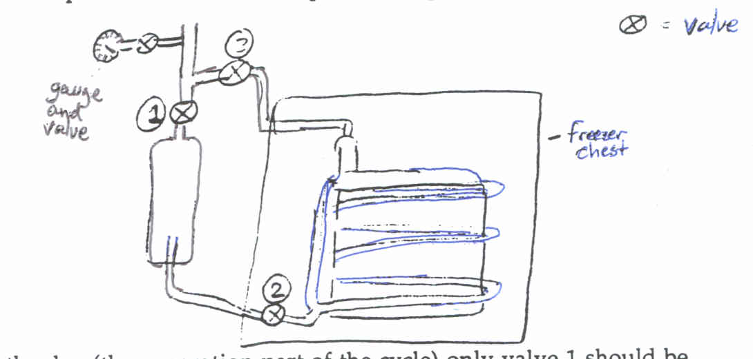
During the day (the generation part of the cycle) only valve 1 should
be open. In this way, ammonia dripping from the condensor coil cannot get
into the evaporator through either valves 2 or 3, and is stored during
the day in the storage tank.
When the generator cools as the sun begins to fade at the end of the
day, valve 1 should be closed. Otherwise ammonia will begin to flow back
to the generator, cooling the storage tank instead of the evaporator inside
the refrigerator.
Once the generator has cooled sufficiently at the end of the day, the
icemaking part of the cycle can be started at any time.
To begin the ice making cycle, make sure that valve 1 is closed, so
that ammonia cannot evaporate back through here. Next open valve 3, so
that evaporated ammonia gas from the evaporator can flow through to the
generator and be reabsorbed by the calcium chloride. The last step, which
requires some playing with, is to open valve 2 to allow liquid ammonia
to flow into the evaporator and begin evaporation. The valve should be
open just enough so that it keeps the evaporator fairly full as the evaporated
ammonia gas flows back to the generator. A more failsafe way to accomplish
this might be to move ammonia in batches into the evaporator: open the
valve halfway and wait for frosting to appear on the upper coils, (which
means that ammonia has reached this high up in the evaporator) and then
shut valve 2. Repeat after a little while (I'm vague here because I just
don't know how long it takes for the evaporator to "use up" all the ammonia
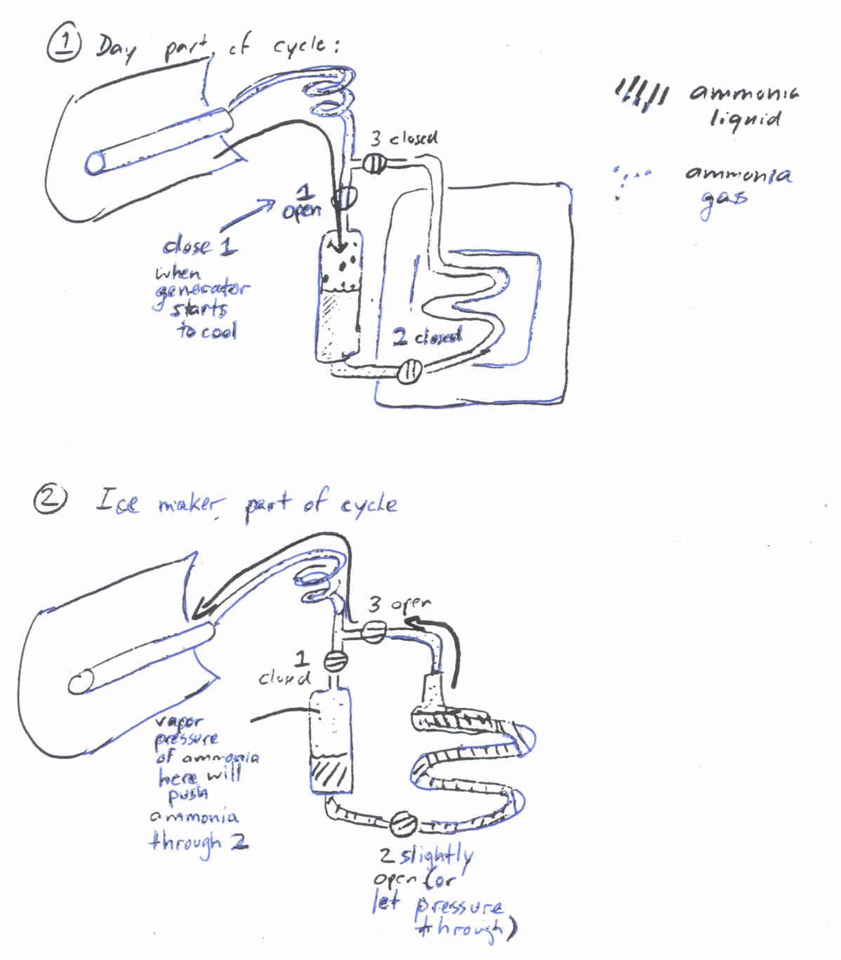
that is put into it) See figures below for an explanation of the generating
and icemaking parts of the cycle and how the valves should be set.
Figure 4
Final Thoughts and Important safety notes:
- It is a good idea to check the focus of the collector every few weeks.
When the collector is in good focus, the shadow of the generator pipe runs
down the centerline of the collector.
- It may be useful, during the ice-making part of the cycle, to have
valve 3 only partly open. This will slow the flow of ammonia gas back to
the generator. Since this gas is cold (it leaves the liquid at the temperature
of evaporation of the ammonia, about -10 F) it helps to keep it in the
insulated space as long as possible by reducing the opening through valve
3. This will, again, require some playing around.
- Important: If the icemaker is to be left for a time without using
it, leave it in the position for daytime generation, with valve 1 open
and valves 2 and 3 dosed. this way, ammonia will cycle back and forth between
the generator and
the storage tank, without a dangerous buildup of pressure during the
day.
- Important: If you need to work on the plumbing, so that the valve
at the exit of the collector /generator (this is the small, round-handled
needle valve between the generator and the condensor coil) must be closed,
make sure to UNFOCUS THE COLLECTOR, or even point it facing north so as
to shade the pipe. This will avoid heating of the pipe. If the pipe is
heated by concentrated sunlight with this valve closed, the ammonia will
have nowhere to condense and extremely high pressures will quickly result.
The advantage of pointing the collector north is that rain will continue
to run off of it rather than gather in the trough of the collector.
Good luck!