INTRODUCTION
People in developing countries spend 90% of their energy
for cooking [1]. If 50% of the world’s
fuel wood-using families switched to using solar ovens, around 346 million tons
of fuel wood would be saved annually [2]. Chez Helios, the Engineers Without
Frontiers (EWF) project team, is working with their partner organization, The
STEVEN Foundation, to perform empirical tests of design parameters for solar
ovens. The improvement and documentation
of solar ovens can benefit people around the world. Solar ovens are not only environmentally
friendly, but they are also pleasant to people’s health and wallets.
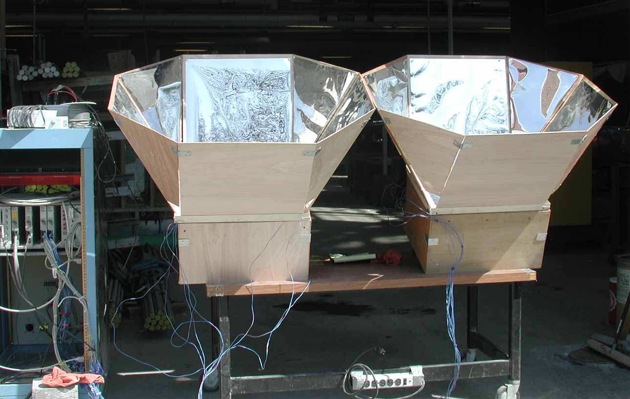
The EWF team members
have built two identical solar box cookers based on the STEVEN Foundation’s plans.
As depicted in Figure 1, these cookers consist of insulated boxes with glass
covers and reflector panes to direct incoming light into the box. In the future, parameters to be tested may
include interior oven coating, amount and type of heat retaining objects used,
insulation, oven door position, and the reflective panel material, shape, and
size. Performance measures include
standardized cooking power and cost to build.
This end-of-semester report
describes our project tasks in detail.
We have provided a schedule for each of these, along with an overall
project schedule for Chez Helios. Our
results from our project are also summarized with a plan for transitioning and
future recommendations. Each of our
group members has provided their reflections from the semester, which give a
personal insight into our project. At
the end, technical documentation is provided to be easily followed by the next
project team.

Figure 1 The two solar ovens made by the team set up for testing
PROJECT
TASK DESCRIPTIONS
The Solar Oven team’s work for this
semester consisted primarily of three main tasks. The first task was to design a solar oven
based on the STEVEN Foundation’s plans, and to build two identical working
models. The second task was to develop a
method of testing the ovens based on the American Society of Agricultural
Engineers (ASAE) standard. Finally, the
third task was to perform the tests. The
team broke up into two subgroups, a building team and a testing team, in order
to accomplish these tasks. However, this distinction was largely for
organizational purposes only; while team members focused more on the task to
which they were assigned, every member worked on both tasks as necessary.
1. Building
The first task for this semester
was designing and building a solar oven based on the STEVEN Foundation’s
model. This was the larger and more
time-consuming of the two tasks, so four team members were assigned to it:
Cheryl, Kien-Man, Jen, and Jeff. During this semester, this team built two complete
ovens and is in the process of building a third. We have also created blueprints for our
design and developed a method of building the ovens that is more detailed and
precise than the STEVEN Foundation’s original plans (See Appendices B and
D).
Francis Vanek of the STEVEN
Foundation provided the team with a solar oven that he had built and used for
several years. We also had a design
manual for the original STEVEN Foundation solar oven (Appendix D). The first major issue that we noticed immediately
was that the design manual describes the oven design as of May 1996, and that
Francis’s oven is a more updated model that does not correspond to the original
design plans. We decided to attempt to
recreate Francis’s oven as closely as possible, making small modifications to
allow for the tools available in the Civil Infrastructure Lab and materials
which we already had or could easily and cheaply obtain. Many of these changes were for our
convenience in either building or testing, and most, we decided, would not
significantly affect the performance of the ovens. In any case, our ability to test various oven
parameters would not be affected by these minor design changes, as long as all
of our ovens are built identically.
Major changes from the 1996 design
manual are as follows:
§
For the outer wooden box (Appendix B.iii-B.iv), we used ¼-inch plywood for the sides and
¾-inch plywood for the base. The manual
calls for using ¾-inch plywood for the entire box; however, Francis’s oven used
¼-inch on the sides. We decided to
follow Francis’s oven, which is the STEVEN Foundation’s most recent model. This
required other design changes due to the lack of wide sides, which were
originally used to rest the reflector panels on. Furthermore, we added 90° angle brackets to
the corners to regain structural stability that was lost in switching to
thinner sides.
§
We built a frame for the glass cover out of 5/8
x 1½ inch wood, miter cut and slotted as shown in our plans (B.vii). The manual suggests
this but gives no instructions for it.
Francis’s oven uses a frame for the glass; however, the fact that his
glass was broken from wear despite the frame suggested the need to design a
better frame.
§
The wood frame at the top of the box was recessed
by ¾ inch, rather than raised above the sides of the box as in the design
manual. This modification was our own
decision and not based on either the manual or Francis’s oven. This change allowed us to fit the door frame
snuggly into the recessed part to prevent it from slipping. Francis’s oven solved this problem by cutting
a recessed step into the frame; however, we did not have the tools to do this
and so we had to opt for a simpler solution.
The dimensions of the outer box were increased to allow for this change
and keep the inside dimensions the same.
§
Due to availability, the metal liner was made of
sheet metal thicker than 26-gauge (as used in the original plans as well as
Francis’s oven). Furthermore, only the
bottom was painted black while the sides were left shiny, as opposed to
painting the entire inside black like that of Francis’s oven. We made this change because in other tests it
had been shown to improve performance [3].
The testing team is considering testing this feature again.
§
For the reflector, eight panels (four
rectangular panels along the sides and four trapezoidal panels in the corners,
as shown in Appendix B.vi-B.vii) were used instead of
the four indicated in the design manual.
This was the major update that the STEVEN Foundation had made since
writing the design manual, and is used in Francis’s oven. As these changes were undocumented, we were
required to build these from scratch, including calculating the necessary
geometry to allow the panels to fit snugly together. As a result, our reflective panels differ
slightly from Francis’s.
§
An additional wooden frame to support the panels
and hold them at a 30° pitch from vertical was designed and built. This added support was necessary because the
eight-panel design was less rigid than the four-panel. Furthermore, the lack of wider box edges
(created from the switch from ¾-inch to ¼-inch wide sides) meant that the
panels would have to rest on something else.
The panel frame rests upon nails in the glass door frame when the oven
is tilted towards the sun. Testing experience revealed that the nails did not
hold the reflector on the box as well as they should have at high angles of
tilt, especially when the reflector panels were blown by the wind. In the
future we will need to develop a more secure method of attaching the reflector
to the box.
§
Tightly packed, rolled newspaper was used for
insulation in our control ovens, as described in the building instructions
(Appendix B.ii).
The original plans and Francis’s oven both used fiberglass insulation;
however, this insulation deforms due to the heat when the oven is used, as we
saw on Francis’s oven. Therefore, we
tried Styrofoam insulation; however, this also melts when the oven heats up. Thus, we decided upon newspaper, which we
know to combust at 233°C, far hotter than our ovens will get. The testing team is considering trying other
alternatives for insulation.
§
Nails, screws, rivets, and other connecting
devices were used as available to us.
Specifically, we used rivets instead of nails to affix the angle
brackets to the reflective panels, and we used 1¼-inch screws instead of 2-inch
nails to attach the frame to the box, as this would make it easier for us to
disassemble the oven to make changes.
These changes were made largely based on the materials available to us
at the time, and they do not significantly affect oven performance.
The end result of the building
team’s work for this semester is two complete ovens, which have been tested to
perform similarly, and updated design plans with detailed notes so that future
teams can build additional ovens identical to ours.
Figure 2 shows a detailed schedule
for the building task. The time to
complete this task was much greater than we had originally expected. Building the first oven involved a great deal
of trial and error due to the fact we were constantly updating and modifying
our design plans. Furthermore, we were
hampered by our initial unfamiliarity with the Civil Infrastructure Laboratory,
and finding time to work with the power tools (which required project
supervisor Tim Bond’s presence, for safety reasons) was often difficult. Although we had hoped to build three ovens by
the end of the semester and give the testing team enough time to run several
tests, it took us about seven weeks to build our first oven and about two weeks
to build our second. However, we now
have a consistent design and familiarity with the building process, so future
teams will be able to devote more of their time and efforts towards testing the
ovens.

Figure
2 Schedule of building
2. Development
of Testing Method
We based our test method off of the
2002 American Society of Agricultural Engineers (ASAE) X580 test standard for
solar cookers (Appendix C). John and Dan implemented the test standard with
slight modifications (Appendix B), following the schedule shown in Figure 3.
The STEVEN Foundation had limited
involvement in this task. They shared their testing experiences, which were
limited to measuring oven temperatures with a crude oven thermometer. We
discussed their results with them, but indicated that we wished to work off the
ASAE test standard because it allows us to compute the standardized cooking
power of the oven, which is more valuable to know than simply how hot the air
inside the oven gets, (which incidentally we are also measuring to be
thorough). The STEVEN Foundation was pleased with our decision to use this
rigorous test method.

Figure
3 Schedule of test procedure development
2.1. Test standard compliance
In order to develop our testing
document, we took the ASAE standard and molded it to fit our needs. In two
instances, we felt it was necessary to lift restrictions placed on testing
conditions due to our climate. First, it called for testing at least 30 ten-minute
intervals over a period of three days (i.e. at least 10 intervals per day).
Given that the statistical likelihood of three consecutive partially sunny days
in Ithaca, NY
is minute, we decided to forgo the requirement that the tests be done on separate
days. Secondly, we also excluded the requirement that the ambient temperature
not fall below 20º C, again due to climate considerations. Waiving these
requirements will have a minimal impact on the usefulness of our results, as
tests at 15°C will not yield very different results than those at 20°C. In
addition, since we will be doing all of our testing with a control oven, we can
gain insight as to the effects of varying a parameter even if a day isn’t quite
up to specs. Testing will take place on the blacktop parking lot behind
Thurston Hall. The lot is well protected from the wind, yet still has good
exposure to the sun.
We decided to comply with the
standard’s requirement of 7.0 kg of water per square meter of incident light area.
This is to make sure the oven is sufficiently loaded as to keep the water from
boiling during the test. All ovens tested thus far have 1.00 m2 of
incident area and therefore require 7 kg ≈ 7.39 qt of water. The method
devised calls for two 4-qt pots painted flat black in order to absorb maximum
amounts of heat. However, we were unable to fit the 7.0 kg in our pots without
the aid of a shelf inside the oven more complex than the crude one we currently
employ. Thus the data in Figures 5, 6, and 7 (B.x-B.xi)
was collected using 3.2 kg of water. We have every intention of using the full
7.0 kg in future tests. The testing done in section three was designed to
compare the two ovens and prove that they performed the same, and thus as long
as we had the same weight in each, using less water did not affect our data.
We have also decided that our
control oven will not be tracked according to the sun’s movements. This will
allow us to study the effect of such tracking and whether it makes a tangible
difference in cooker performance.
2.2. Data collection
The data collection system is
largely based on a pre-existing system owned and maintained by the Civil
Infrastructure Lab. The data collection system includes a weather station which
monitors wind speed, wind direction, and ambient temperature. We purchased a
radiation pyranometer (required by the standard),
which measures the insolation in W/m2 at
any given time. This is important because it allows us to characterize the
power generated by the oven in relation to the energy given to it by the sun.
We are then able to compare a test on a partly-sunny day with a test on a very
sunny day. The power during each interval is adjusted for the amount of insolation, thus allowing a measurement of the oven’s power
independent of the solar power given to it (Appendix C).
The apparatus also includes eight
thermocouples per oven, which are used to monitor temperatures at crucial
spots. In another deviation from the test standard, we chose to use seven more
thermocouples per oven in order to gain additional information about the
performance. The test standard requires only a thermocouple inside each water
vessel and outside the oven for ambient conditions. Our method monitors the
temperature on either side of the insulation, on either side of the glass
cover, and of the air inside the oven. Our data is collected every 30 seconds,
giving us maximum flexibility in choosing our ten-minute intervals. Every
ten-minute interval in which environmental conditions stated in Appendices B and
C hold is valid and included in analysis.
3. Testing of control
ovens
Combining both previous tasks, we
used our test method on the first oven we built, as shown in the schedule in Figure
4. This showed numerous improvements that could be made to the first oven,
including the substitution of a different insulation material. During this
test, our Styrofoam insulation melted onto the metal lining, yielding a big
mess and unappetizing smell. When we discussed the insulation problem with him,
Francis suggested that rock wool, straw, or newspapers be considered as
alternative insulation materials. In addition, another layer of wood between
the metal lining and the insulation could also do the trick, he said. For later
tests, the control oven was insulated with crumpled newspaper. Other issues
that still need to be addressed include the sealing of the metal liner with
caulk (which we are hesitant to do until we find insulation we are happy with)
and the installation of pins to hold the glass cover and reflectors in place.
The data collection went very well, and the method was successfully executed.
Ways of supporting and tracking the oven (moving it with the sun throughout the
day) were examined and we ultimately found props for the cooker that would hold
it at the proper angle and a shelf for the pots to keep them level. These are
crude and a modification of these props and shelf would allow us to place the
cooker at a more ideal angle with respect to the sun, increasing our power.
Upon the completion of the second
oven, we tested both ovens simultaneously using our test method. As mentioned
briefly earlier, we have not yet acquired the proper water vessels to allow the
use of 7.0 kg per oven. Thus the water did boil and we had to throw out all the
data intervals after the water had reached 95°C. However, there was meaningful
data gained from this test, namely that the two ovens were nearly identical in
performance (Figures 6 and 7, B.xi). The standardized
cooking power at 50°C
was 81.1 W for Oven 1 and 82.7 W for Oven 2, and their data plots
(Figure 6) are nearly identical as well. This is exactly what we were hoping
for because it will allow us to make a modification of Oven 2 and use Oven 1 as
a control.

Figure
4 Timeline of other testing tasks
OVERALL PROJECT PLAN
Overall project schedule

Summary of semester outcomes
Our group successfully achieved the
following:
- Developed construction blueprints and instructions
for building a solar box cooker (based on existing STEVEN Foundation model
and plans).
- Constructed two unmodified solar box cookers.
- Developed a set of testing procedures that meets the
ASAE X580 test standards.
- Set up a testing station capable of testing two ovens
simultaneously.
The work done in
this semester will act as a solid foundation for future solar oven testing.
Future teams can use and expand the testing station that we have set up to
simultaneously test several modified ovens with a control oven. To speed up
testing, future teams will want to use our construction blueprints to create
1-2 more standard solar ovens, and then modify them as needed.
With input from
the STEVEN Foundation, our group has come up with several ideas for
modifications to test. The modifications were chosen because they are feasible
changes that could improve cooker performance, and very little data currently
exists on how they affect performance:
- Double glazing the oven door
- Using another type of insulation
- Painting the interior oven sides flat black
- Placing a large thermal mass in the oven to improve
heat retention
- Using different reflective materials
Transition Plan
Summer solar
oven testing will be a continuation of this semester’s goals, and ultimately a
bridge to the fall semester. The group
consisting of Cheryl Bauer and Brian Warshay, with
Tim Bond supervising, will use the solar ovens built during the spring
semester, along with the testing station, to measure different components of
the oven itself and the environment surrounding it. During the summer, the team
will test the effects of the above-mentioned modifications on oven performance.
Other modifications that the group comes up with might be tested as well. Also, a third oven will be constructed
identical to the two created during the spring semester, and it too will be
modified and tested. We used SA-85, a
hi-tech 3M product, for reflective material on the first two ovens.
Unfortunately, this product is no longer made and we used our entire stock of
it. An alternative reflective material will have to be used on the third oven.
When testing variables other than reflective material, the material on all
three ovens should be the same, so the summer group will likely also have to
replace the SA-85 material on the first two ovens as well. VM2000 is a similar
product made by 3M that could be substituted, but it is not UV-protected.
VM2000 would have to be coated for UV protection in order to stand up to
prolonged exposure to sunlight.
The main goal of
the summer is to achieve the original project plan for this semester,
including: testing different variable parameters to determine quantitatively
the effect they have on oven performance and collecting results to place in an
organized database that will be published. In addition, the design notebook
from the spring, and a notebook created during the summer will be accessible to
the solar oven group in the fall.
CONCLUSIONS AND RECOMMENDATIONS
Solar ovens have been the source of
much unofficial research in the past ten to fifteen years; the solar box cooker
is just one of many designs. Although
several extensive manuals detail qualitatively the effects of varying certain
parameters (reflective material, shape of collectors, etc.), there is little
hard data available from official experiments conducted using the ASAE test
standard for solar ovens [4, 5].
The primary objective of this
project was to experimentally collect standardized, empirical data about solar
ovens. This will augment the already
available qualitative material and aid in further advancement in the field of
solar ovens. Solar ovens are valuable
for a variety of reasons, to a variety of populations. We did not intend to develop an oven to
install in a particular location in the short term,
rather we were concerned with developing quantitative data for the solar oven
community in general, and specifically, our partner organization, the STEVEN
Foundation. Installing these ovens
somewhere would be a great future project.
This semester, we learned that
working through the building of the first oven as a team step-by-step made the
construction of the second oven much smoother once we effectively divided into
separate teams. Our group effectively
accomplished building two solar ovens that we are very proud of and an
effective testing method with standards.
While working these past four months, we kept accurate records and
accounts of our every move making it easier for the next group to pick up where
we left off. We have set solid groundwork
for the ovens, and now the modification is ready to begin.
REFERENCES
1. Sperber, Bill. “Balancing the Scales.” The Solar Cooking
Archive. 7 Apr. 1990.
<http://solarcooking.org/balance.htm>
2. “The
Untapped Market for Solar Cookers.” The Solar Cooking Archive.
<http://solarcooking.org/market.htm> Feb. 2004.
3. “Solar
Cooking Frequently Asked Questions.” The Solar Cooking
Archive. <http://solarcooking.org/solarcooking-faq.htm> August 2001.
4. “The Bernard Solar Panel Cooker.” <http://p2.utep.edu/watts/manuals/bernard.pdf>
5. “The Solar Cooking Archive.” <http://solarcooking.org
Appendix: ASAE STANDARD X580
ASAE Standard: ASAE X580 (SE-414 Voting Draft revised by P.
Funk on 04/03/2002)
Testing and Reporting Solar Cooker Performance
Developed by the Test Standards Committee at the
Third World Conference on Solar Cooking (Coimbatore,
Tamil Nadu, India, 9 January 1997); editorial
revisions November 1998 and July 1999; revised March 2001 (Third Latin American
Congress on Solar Cookers, La Ceiba, Atlintico, Honduras); edited and submitted for approval to
ASAE Solar Energy Committee SE-414 (94th Annual International
Meeting, Sacramento, California, USA) 31 July 2001; revised and resubmitted 15
March 2002.
SECTION 1 — PURPOSE AND
SCOPE
1.1
This Standard is intended to
1.1.1
Promote uniformity and consistency in the terms and
units used to describe, test, rate and evaluate solar cookers, solar cooker
components, and solar cooker operation.
1.1.2
Provide a common format for presentation and interpretation
of test results to facilitate communication.
1.1.3
Provide a single measure of performance so
consumers may compare different designs when selecting a solar cooker.
1.2
The scope of this Standard includes
1.2.1
All solar powered batch-process food and water heating
devices (solar cookers). Devices
designed to desiccate (dryers) are not covered.
1.2.2
Within the scope of this Standard a solar cooker
shall be understood to include the cooking vessel(s) together with associated
supporting, heat transfer and heat retention surfaces, heat storage and
transfer media and associated pumps and controls, light transmitting and
reflecting surfaces, and all associated adjustments, supports, and solar
locating and tracking mechanisms as may be integral parts of a particular solar
cooker.
SECTION 2 — NORMATIVE
REFERENCES
IS 13429. 1992. Indian Standard- Solar Cooker- (3 Parts). Bureau of Indian Standards, New Delhi.
SECTION 3 — TERMINOLOGY
3.1
Absorber plate: Darkened surface converting light energy into
thermal energy.
3.2
Angle, Azimuth: The angular displacement
from south of the projection of beam radiation on the horizontal plane.
3.3
Angle, Zenith: The angle subtended by a
vertical line to the zenith (point directly overhead) and a line directly to
the sun.
3.4
Beam Radiation: Solar radiation received
directly from the sun without atmospheric scattering.
3.5
Box-type cooker: A solar cooker with a well-insulated volume
for the cooking vessel(s), typical designs having from zero to four plane
mirrors.
3.6
Concentrating-type cooker: Any of various designs characterized by
multiple plane or curved reflective surfaces. Many designs lack insulated walls but have
large intercept areas to compensate for their comparatively greater heat loss.
3.7
Intercept area: The sum of the reflector and aperture areas
projected onto the plane perpendicular to direct beam radiation (Figure
1). For convenience, use the average
beam radiation zenith angle as calculated for the entire test period.
3.8
Load: The mass of water being heated by the
solar cooker.
3.9
Test: All
events and data comprising the measured solar heating of water in a device
intended to cook food.
3.10
Tracking: Rotating the cooker in the
horizontal plane to compensate for azimuth angle changes (box-type) or
following the sun in two dimensions (concentrating-type).
SECTION 4 — GENERAL
4.1 This Standard specifies that test results be presented as
cooking power, in Watts, normalized for ambient conditions, relative to the
temperature difference between cooker contents and ambient air, both as a plot
and as a regression equation for no less than 30 total observations over three
different days.
4.2 This Standard specifies that cooking power be presented as
a single number found from the above equation for a temperature difference of
50 C.
SECTION 5 — UNCONTROLLED (WEATHER)
VARIABLES
5.1 Wind. Tests shall
be conducted when wind is less than 1.0 ms-1, measured at the
elevation of the cooker being tested and within ten meters of it. Should wind exceed 2.5 ms-1 for
more that ten minutes, discard that test data.
If a wind shelter is required, 1) it shall be designed so as to not
interfere with incoming total radiation and 2) The wind instrumentation shall
be co-located with the cooker in the same wind shadow.
5.2 Ambient temperature. Tests should be conducted when ambient
temperatures are between 20 and 35 C.
5.3 Water temperature.
Test data shall be recorded while cooking vessel contents (water) is at
temperatures between 5 C above ambient and 5 C below local boiling temperature.
5.4 Insolation. Available solar energy shall be measured in
the plane perpendicular to direct beam radiation (the maximum reading) using a
radiation pyranometer. Variation in measured insolation
greater than 100 Wm-2 during a ten-minute interval,
or readings below 450 Wm-2 or above 1100 Wm-2 during the
test shall render the test invalid. For
convenience, the pyranometer may be fixed on the
cooker at the average beam radiation zenith angle as calculated for the entire
test period.
5.5 Solar zenith and azimuth
angle. Tests should be conducted
between 10:00 and 14:00 solar time.
Exceptions necessitated by solar variability or ambient temperature
shall be specially noted.
SECTION 6 —CONTROLLED (COOKER)
VARIABLES
6.1 Loading. Cookers shall have 7.0 kg potable water per
square meter intercept area distributed evenly between the cooking vessels
supplied with the cooker. If no cooking
vessels are provided, inexpensive aluminum cooking vessels painted black shall
be used.
6.2 Tracking. Azimuth angle tracking frequency should be
appropriate to the cooker’s acceptance angle.
Box-type cookers typically require adjustment every 15 to 30 minutes or
when shadows appear on the absorber plate.
Concentrating-type units may require more frequent adjustment to keep
the solar image focused on the cooking vessel or absorber. With box-type cookers, zenith angle tracking
may be unnecessary during a two hour test conducted at mid-day. Testing should be representative of local
conditions, ie; how the typical
consumer is expected to use the cooker.
6.3 Temperature sensing. Water and air temperature should be sensed
with thermocouples. Each thermocouple junction shall be immersed in the water
in the cooking vessel(s) and secured 10 mm above the bottom, at center. Thermocouple leads should pass through the
cooking vessel lid inside a thermally nonconductive sleeve to protect the
thermocouple wire from bending and temperature extremes. The sleeve should be secured with 100%
silicone caulk to reduce water vapor loss.
6.4 Water mass. The
mass of water should be determined with an electronic balance to the nearest
gram using a pre-wetted container.
SECTION 7 — TEST
PROTOCOL
7.1 Recording. The average water temperature (C) of all
cooking vessels in one cooker shall be recorded at intervals not to exceed ten
minutes, and should be in units of Celsius to the nearest one tenth of a
degree. Solar insolation
(Wm-2) and ambient temperature (C) shall be recorded at least as
frequently. Record and report the
frequency of attended (manual) tracking, if any. Report azimuth angle(s) during the test. Report the test site latitude and the date(s)
of testing.
7.2 Calculating cooking
power. The change in water
temperature for each ten-minute interval shall be multiplied by the mass and
specific heat capacity of the water contained in the cooking vessel(s). This product shall be divided by the 600
seconds contained in a ten-minute interval, as:
P = (Tf - Ti)MCv/600 [1]
where:
P = cooking power (W)
Tf = final water temperature
Ti = initial
water temperature
M =
water mass (kg)
Cv =
heat capacity (4186
Jkg-1K-1)
7.3 Calculating interval
averages. The average insolation, average ambient temperature, and average
cooking vessel contents temperature shall be found for each interval.
7.4 Standardizing cooking
power. Cooking power for each
interval shall be corrected to a standard insolation
of 700 Wm-2 by multiplying the interval observed cooking power by
700 Wm-2 and dividing by the interval average insolation
recorded during the corresponding interval.
Ps =
Pi(700/Ii) [2]
where:
Ps =
standardized cooking power (W)
Pi =
interval cooking power (W)
Ii =
interval solar insolation (Wm-2)
7.5 Temperature difference. Ambient temperature for each interval is to
be subtracted from the average cooking vessel contents temperature for each
corresponding interval.
Td =
Tw – Ta [3]
where:
Td =
temperature difference (C)
Tw = water temperature (C)
Ta =
ambient air temperature (C)
7.6 Plotting. The standardized cooking power, Ps,
(W) is to be plotted against the temperature difference, Td, (C) for
each time interval.
7.7 Regression. A linear regression of the plotted points
shall be used to find the relationship between cooking power and temperature
difference in terms of intercept (W) and slope (WC-1). No fewer than 30 total observations from
three different days shall be employed.
The coefficient of determination (r2) or proportion of
variation in cooking power that can be attributed to the relationship found by
regression should be better than 0.75 or specially noted.
7.8 Single measure of
performance. The value for
standardized cooking power, Ps, (W) shall be computed for a
temperature difference, Td, of 50 C using the above determined relationship.
NOTE: for product labeling and sales literature an
independent laboratory using a statistically adequate number of trials shall
determine this number. While this value,
like the fuel economy rating of an automobile, is not a guarantee of performance,
it provides consumers with a useful tool for comparison and product selection.
7.9 Reporting. A plot of the relationship between
standardized cooking power and temperature difference shall be presented with
the equation, following the example in Figure 2. The report shall also state the standardized
cooking power at a temperature difference of 50 C.
SECTION 8 —
REFERENCES
Funk, P.A. 2000.
Evaluating the international standard procedure for testing solar
cookers and reporting performance. Solar Energy 68(1):1-7.
Mullick S.C., Kandpal
T.C. and Saxena A.K. 1987.
Thermal test procedure for box-type solar cookers. Solar Energy 39(4), 353-360.